Improving Quality of Testing
Fast and Error-Free Pin Mapping of Custom Cable Test Fixtures
Every electronics manufacturer testing cables and wire harnesses eventually encounters the same inflection point: the product under test doesn't match any standard connector interface. A defense avionics harness with 23-pin circular MIL-spec connectors. An industrial PLC cable terminated in a proprietary rectangular housing. A medical device assembly with six different connector types on a single harness. At that moment, a custom test fixture becomes not just an option, but a necessity, and with it comes the critical question of how to map that fixture to the test system accurately and efficiently.
When Standard Boards Aren't Enough
Automated cable and harness testers can be readily configured with auto-detected, plug-in connector boards for fast, convenient set-up and testing of standard cables. Stock fixtures cover the most common interface types such as DB9, DB25, RJ45, USB, DVI, HD15, and similar everyday connectors. These boards serve most general-purpose testing needs well. The CableEye® family of testers from CAMI Research (referenced throughout this article) is representative of this class of instrument. Its tester interface consists of standard 64-pin dual-row latch headers, each bank of 64 test points accepting plug-in connector boards directly (Fig. 1) or flat-cable/AMPMODU wire connections to external fixtures (Fig. 2).
That architecture is deliberately flexible: The same physical interface that accepts a standard plug-in board can equally accept a custom-wired pigtail (Fig. 1b), or a wired connection to an external panel (Fig. 2) or mating harness board, giving engineers broad latitude in how they design their test interface for any given application. But regardless of platform, the electronics industry employs a virtually uncountable variety of connector types, and standard boards represent only a fraction of what engineers encounter in the field.
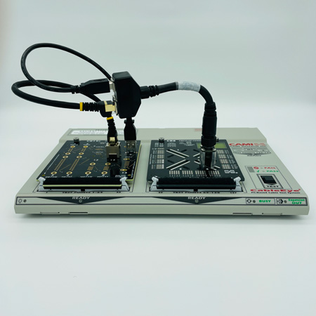
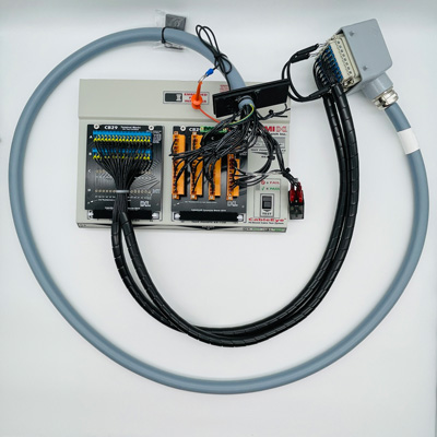
Figure 1: Auto-Detected Plug-In Board Custom Interface Fixtures With Test Cables a) With universal CB8 (bank 2); b) With pigtail for large, heavy connector
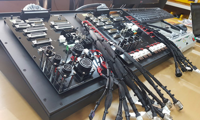
Figure 2: Auto-Detected Panel Interface Fixture With AMPMODU Cable Connections to HiPot Tester
Photo: Incoretech
When the cable or harness under test includes connectors not found on any standard board, that flexibility becomes essential. Test engineers can choose from a range of interface approaches depending on the application. For smaller setups with fewer than about ten connectors, untethered pigtail adapter cables (short cables with a custom mating connector on one end and a standard 64-pin dual-row connector on the other, plugged directly into the tester's 64-pin headers), offer a quick and inexpensive solution (Fig. 3). For more permanent setups, custom connectors can be mounted directly on blank prototyping boards such as the CableEye CB8 (up to 64 test points) or CB30 (up to 128 test points), which plug into the tester just like any standard board (Fig. 1a).
When connector pin density or proximity demands it, a fully custom-designed PCB can be fabricated to fit the same fixture footprint. For large wire harnesses spread across a broad physical layout, a dedicated mating harness board (essentially a mirror-image of the device under test with complementary mating connectors routed back to the tester via flat/AMPMODU cable ) provides the most comprehensive solution. And when the number or size of connectors makes board-mounted solutions impractical, a rack- or bench-mounted external connector panel, wired back to the tester's 64-pin headers, keeps everything accessible and organized (Figs. 2, 4). The choice of method is left entirely to the engineer, and in practice many test setups combine more than one approach on the same fixture.
Each of these approaches gets the hardware connected. But hardware is only part of the story.
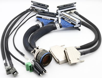
Figure 3: Untethered Pigtail Adapters
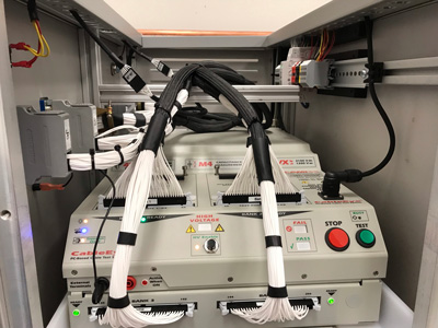
Figure 4: Cable Routing of Rack-Mounted Test System
The Translation Problem and Where Errors Creep In
Once the physical interface is in place, the test system needs to know what it is looking at. When a cable
tester measures continuity, it works with raw test point numbers i.e. abstract identifiers that mean
nothing to a technician trying to isolate a fault. Without a translation layer, a reported short between test
points 47 and 52 requires a manual lookup through a paper table to determine that those numbers
correspond to pins B and G on connector J3. That lookup takes time, introduces transcription risk, and
creates exactly the kind of human error that automated testing is supposed to eliminate.
The pin map is that translation layer. It links each physical pin on a custom mating connector to its
corresponding test point number, and associates a graphical connector image and meaningful pin label
with each connection. When the map is correct, a fault reported between pin B and pin G on J3 is
immediately actionable. When the map contains errors, the test system reports incorrect results, and
confident, wrong test results are worse than no results at all.
Map errors tend to fall into predictable categories. A technician who leaves the cable under test connected while probing the fixture will inadvertently map the cable's wiring rather than the fixture itself, producing a map that is corrupted from the start. Forgetting to assign a test point to a pin that will later carry wiring results in that conductor appearing as belonging to an unmapped "header" on the screen rather than its correct connector. Reversing the assignment of two pins produces a map that looks complete but reports wiring errors even on correct cables; this is a particularly insidious failure mode, since no error message flags the problem. Sharing test point assignments between connectors in a fixture map, which is not permitted (though it is allowed in relocatable CB Board maps), causes a conflict that blocks the map from functioning. And attempting to create a CB Board map while the board is connected to any bank other than Bank 1 introduces offsets that invalidate the entire map.
Software as the Primary Defense Against Error
The most effective way to minimize all of these error types is to use purpose-built mapping software rather than creating and managing lookup tables manually. CAMI Research's optional PinMap™ fixture editor is embedded directly within the CableEye software environment and is designed specifically to eliminate the manual, error-prone approaches that compromise map accuracy.
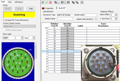
The core workflow is probe-driven. Once a fixture is built and connected to the tester, the technician clicks <Scan> in the PinMap interface to activate a continuous probe mode.
Touching the probe to each pin on the mating connector causes the software to detect the corresponding test point number automatically and enter it into the grid without typing, transcription, or reference to a separate document (Fig. 5, video).
The software advances to the next pin in sequence after each successful contact, and a synthetic voice reads the detected pin number aloud so the technician's eyes can remain on the connector throughout the process. The entire mapping session proceeds as fast as the probe can be moved from pin to pin.
The software includes a dedicated Test mode specifically designed to certify a completed map before it
is put into use. In Test mode, the technician touches the probe to connector pins in any order; the
corresponding pin highlights on the on-screen connector graphic and its grid row is selected
simultaneously. If a pin on the physical connector causes the wrong graphic pin to light up, a reversal
error is immediately apparent and can be corrected before a single cable is tested with the bad map.
The PinMap editor also detects and flags structural errors automatically. If a test point assignment is
duplicated across connectors in a fixture map, the offending entries are highlighted in red when the
technician attempts to save. If the probe session includes test points from a cable inadvertently left
connected to the fixture, the resulting short detections prevent the map from completing in any
meaningful form, prompting the technician to start over with the cable disconnected. These guardrails
catch the most common mistake categories before they can propagate into the cable database.
Beyond error prevention, the PinMap editor supports custom pin labeling with up to seven alphanumeric characters per pin. For wire harness applications where connector designators like J1:14 or P3:SH must appear in test reports to match schematic documentation, the label generator can populate these automatically during the probe session, creating a fully labeled map at the same speed as an unlabeled one. Connector maps can also be copied and pasted between fixture files, allowing a technician to probe one instance of a repeated connector and replicate it with a test point offset for subsequent instances. This is a significant time saver on harnesses with identical connector blocks.
Immediate Clarity When Faults Are Found
The practical value of a correctly mapped fixture extends to every subsequent test. When PinMap
software has been used to define the interface, all fault reports (shorts, opens, miswires) reference the
actual pin designations of the unit under test, not arbitrary test point numbers. A short between pin B
and pin G on J3 is reported precisely that way. The operator knows immediately where to look. No
lookup table. No intermediate translation step. No additional opportunity for human error between the
test result and the corrective action.
For operations that test numerous cable variants across multiple custom fixtures, PinMap map files are
saved to a named database, selectable from a menu within the CableEye application. Once a cable is
learned and saved in association with a fixture map, that map is restored automatically whenever the
cable is loaded for future testing, eliminating any chance of a mismatch between the fixture in use and
the map the software is applying.
Custom fixture testing does not have to mean accepting a higher rate of setup errors or investing
engineering time in maintaining manual translation tables. Probe-driven mapping software shifts that
burden from human attention to automated verification, and the result is faster setup, more reliable
results, and faults that mean exactly what they say.
Explore a practical example of how PinMap software is used to map a custom cable test fixture.
CableEye Testers for Checking Connection Resistance
With the exception of M2-series testers, all models of CableEye testers can be used to check the quality of good connections and good non-connections (i.e. isolation).
CableEye Testers with HiPot Capability
CableEye Testers with 4-Wire Measurement Capability
M4
4-Wire measurement capability with ±0.02 Ω resolution is a standard feature.
HVX Series
Advanced Measurements Option, Item 833, includes 4-wire measurement capability with ±0.02 Ω resolution. This option must be ordered at time of purchase of the control module.4-Wire Kelvin Resistance Measurement Option, Item 832, provides 4-wire measurement capability with ±0.001 Ω resolution. This option can be retrofitted.
CableEye ® Automation-Ready Cable and Wire Harness Test Systems
CableEye testers are highly versatile, expandable and upgradable diagnostic and Pass/Fail check Cable and Harness Test Systems that are PC-based. They are used for assembly, prototyping, production, and QC of standard or custom wire cables and harnesses The entire suite of products is powered by the same easy-to-use operating software and, with the help of its signature easy-to-interpret color-coded graphics, instantly identifies not only when there is a fault, but what type of fault and where.
Low Voltage M2 Series
For diagnostic and Pass/Fail Testing - Find, display, log, & document continuity (opens, shorts, miswires, intermittent connections).
Low Voltage M3 Series
For all of the above plus resistance (contact, isolation, embedded), and diodes (orientation, forward voltage, reverse breakdown).
Low Voltage M4 Series
For all of the above plus precision resistance (4-wire), and capacitance (twist wire relationship, length of cable, length to break, capacitors).
Low Voltage and High Voltage HVX Series
For all as described for M3 plus HiPot (dielectric withstand voltage and insulation resistance). 4-Wire Kelvin Measurement and Advanced Measurement Options (capacitance, twist wire relationship, length of cable, length to break, capacitors) are available.
Try One!
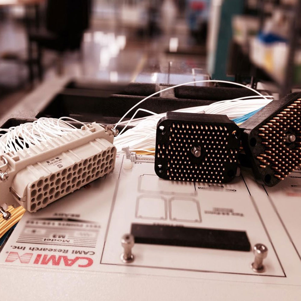
photo credit: Progressive Image
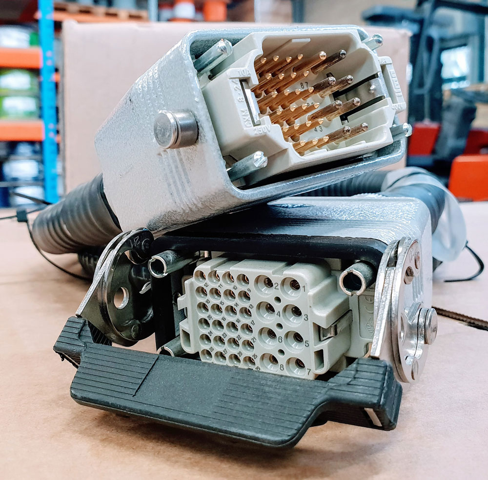
photo credit: AP Technology
"Our production guys find it simple to setup and use. Our clients love it as it provides complete traceability for each and every cable assembly we manufacture."
AP Technology, UK