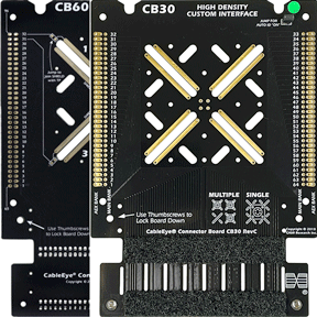
The CB60 looks similar to the CB30, but is designed to operate at higher voltage.
As long as the connectors under test are suitably voltage-rated, the board configurations you see below may be realized with either the CB30 or CB60.
Clearly, high voltage testing requires an HVX-series tester.
See how these boards are customized for diverse test applications — examples and photos below.
+1 978 266 2655
Explore Additional Industry Applications
CableEye® technology is used across a wide range of industries and testing scenarios beyond those represented within the tabs of this page. Explore additional application examples showing how industry applies CableEye test systems to different cable types, test requirements, and production environments.
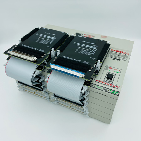
1 - M3Z (768 TPs) continuity tester fitted with stock, interchangeable, plug and play, quick-connect CB30D interface fixtures for testing cables terminated with LFH200 connectors.
Each CB30D daughter board is mounted to a CB30.
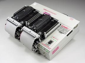
The test unit shown comprises a control module and five expansion modules and can be further expanded to a total of 2560 test points.
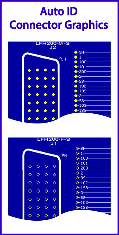
The auto ID connector graphics for the LFH connectors appears below.
Application: Computing, IT, Test and Measurement Products

3 - We designed the CB30B daughter board shown here to mount on the CB30 board to interface the Cannon DL-156 ZIF (zero insertion force) connectors. This 384-point CableEye system provides three 64-pin banks for each connector. The CB30 board can also be configured for Cannon DL-96 and DL-60 connectors.
The auto ID connector graphic for the DL-156 appears below.

4 - This CB30 board secures an adapter cable for a 128-pin high-density circular connector. Nylon lacing and wire-ties are used to route and secure the wiring leading to the terminal pads.

5 - We mounted two independent circular connectors on this CB30. Because the customer wanted both connectors on the same board and more than 64 test points were required to do this, we used a CB30 (128-points maximum) instead of a CB8 (64-points maximum). The board is wired from the back, and if you look carefully, you can see some of the wiring through the unused slots.
The upward-facing connector in the front takes a 64-conductor flat cable that connects to an expansion module to obtain the additional test points needed.


